

Flowmeters & Flowmeter Accessories
Liquid Flowmeters
Turbine, Magnetic and Ultrasonic, Positive Displacement, Coriolis/Mass, Open Channel
Steam Flowmeters
Differential Pressure, Vortex
Gas Flowmeters
Thermal Mass, Variable Area
Turbine Flowmeters

To measure clean liquids like water or liquids with viscosity close to water, turbine meters are often used because they are relatively inexpensive in smaller sizes, produce a low pressure drop, and can handle minor particulate matter. Electronic turbine meters have internal rotors with multiple blades. As the flow velocity increases, an electronic pick up coil senses the faster rotation of the blades. The velocity of the rotation is proportional to the flow rate.
Some turbine meters can be provided with mechanical gearing and registers to show flow rate and total and also with pulse and analog output signals for recording and control purposes.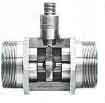 For chemical service, the turbine meter can be constructed with materials to provide compatibility with the fluid. For example, the meter bodies and internals can be offered in various combinations of stainless steel, CPVC, Kynar, Teflon, Hastelloy C, and Titanium to help withstand corrosive fluids.
Turbine meter accuracy can range from ± 0.25% to ± 3%. Sizes generally are 1/32” to 24” with typical turndown ratios of 10:1. Approximate straight pipe run requirements are 15 pipe diameters upstream and 5 downstream.
Click here to request a quote for a turbine flowmeter.
Magnetic and Ultrasonic Flowmeters

For fluids with higher viscosity than water, magnetic and ultrasonic meters are popular choices because they are immune to viscosity changes. Since these meters do not have internal parts which can disrupt the flow they also produce very small pressure drops. As a result they can handle fluids with debris and particulate such as wastewater and cement or pulp slurries.
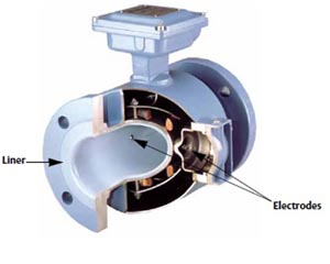
Magnetic flowmeters consist of coils mounted on the outside of a non-magnetic pipe section, or on the outside of a lined pipe section if it’s a conductive material such as stainless steel. As voltage is applied to the coils, current passes through them which generates a magnetic field inside the pipe section. As conductive liquid passes through the pipe section it is perpendicular to the plane of the magnetic field. This flow generates a voltage which is extracted through a pair of electrodes installed on opposite sides of the pipe. The voltage produced is proportional to the fluid velocity. A transmitter or converter is used to amplify and condition the voltage, usually to a 4 to 20 mA DC current representing the flow rate.
Typically the minimum conductivity of the fluid needs to be in the 1-5 microsiemens/cm range. As a result magnetic flow meters won’t work for most gasses and petroleum products. Magnetic flowmeters can provide accuracy from ± 0.2% to ± 2% with turndowns as high as 100:1 and sizes from 1/8” to 96”. Approximate straight pipe run requirements are 5 pipe diameters upstream and 3 downstream.
A very significant new feature with Rosemount Magnetic Flowmeters is a Meter Verification diagnostic. This provides a means of verifying the flowmeter is within calibration without requiring a process shutdown or a costly removal of the meter to send it out for a calibration check to meet federal and/or state requirements.
Ultrasonic flowmeters usually have sensing elements clamped to the outside of the pipe, but they may also be immersed in the fluid. Doppler ultrasonic flowmeters require particles or bubbles in the fluid. If the ultrasonic frequency sent is equal to the frequency received back after it travels through the fluid, there is no flow. The meter measures the frequency shift that occurs with flowing fluid. The flow rate is proportional to the frequency shift which increases with fluid velocity.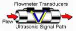 Time of flight or Transit Time ultrasonic flowmeters are used to measure clean fluids. The meters require two sensors, one upstream and one downstream. An ultrasonic wave is sent through the fluid from one transducer to the other and the travel time of the wave is electronically measured. Another wave is then sent from the second transducer to the first and its travel time is also measured.
The difference in travel time between the opposing waves is proportional to the fluid velocity. An electronic converter uses the difference to calculate a flow rate.
Click here to request a quote for a magnetic flowmeter.
Positive Displacement
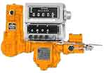
A positive displacement meter is often used for higher viscosity fluids, however liquids with water like viscosity are also suitable for measurement. For fuel oils, nutating disc or oval gear meters are available from ¼” through 2”. Birotor meters are used for larger line sizes. Other types include helical gear, piston, lobed impeller and sliding vane meters. These types of flowmeters entrap a known quantity of fluid per rotation in the meter body. The rotation is translated into pulses which are totaled up over time to produce a flow rate. Positive displacement meters work over wide viscosity ranges with minimal effects on accuracy, however the pressure drop rises as the viscosity increases. Positive displacement meter accuracy is generally ± 0.5% to ± 1% with turndown ratios from 10:1 to 200:1. Meter sizes range from ¼” to 16”. Straight pipe runs are not required.
Positive displacement meters can be provided with mechanical registers to be used in areas where electric power is not available or not desired.
Click here to request a quote for a positive displacement flowmeter.
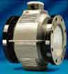
Coriolis / Mass Flowmeters
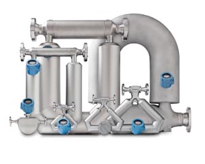
Mass flow meters are a good choice when a non-intrusive meter is required but magnetic or ultrasonic meters are not suitable. These meters directly measure the mass flow of liquids and gasses. Although their cost is higher than other meters of similar line sizes, there are no moving parts in the meter which keeps maintenance costs down.
These meters also provide additional measurements such as density, temperature, and volumetric flow which help offset the higher cost. They are able to measure difficult fluids such as corrosives, slurries, and sludges. In addition the food and beverage industries take advantage of the density measurement to monitor liquid concentrations such as sugar. Line sizes range from 1/8” through 6”. Mass flowmeter accuracy varies from ± 0.1% to ± 1% with typical turndown ratios of 20:1 to 100:1. Straight pipe runs are not required.
Click here to request a quote for a coriolis / mass flowmeter.
Open Channel Flowmeters
These meters are microprocessor based ultrasonic transmitters or controllers. They actually measure fluid level in flumes, weirs, and open flow nozzles. The level measurement is converted to flow rate and total using standard flow equations which are stored in the meter’s microprocessor memory.
Most units are provided with pre-programmed flow equations for the most common flume, weir, or nozzle sizes. For specific or unique applications, a site specific level to flow conversion table can be entered and stored in the microprocessor. Open channel flow meters are usually found in wastewater treatment plants and in commercial and industrial plants to measure plant influent and effluent. These flowmeters provide accuracies from ± 0.5% to ± 5%. They can be used to measure all sizes of flow streams from 6” flumes or weirs to river flows. Flumes and weirs are generally constructed to provide straight runs to allow a relatively calm liquid surface at the measurement point.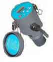 Click here to request a quote for an open channel flowmeter.
Differential Pressure Flowmeters
Steam flows are most often measured using a flow element which develops a pressure differential between a pressure connection on the upstream or high pressure side of the element and another pressure connection on the downstream or low pressure side of the element. Common elements used are annubars, pitot tubes, orifice plates, v-cones, venturis or wedges.
The two pressures are piped to a differential pressure transmitter. Standard flow calculations for the element are used to determine the relationship between the flow rate and the differential pressure. Factors such as pressure, temperature, density of the steam, and the flow area of the pipe and the elements are used in the flow formula for the element. The transmitter is usually then calibrated to convert the differential pressure to a 4 to 20 mA output which represents the flow rate.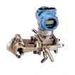 Since steam flow rate is significantly affected by the pressure and temperature of the steam, separate measurements of these variables are made in situations where they fluctuate significantly. Multi-variable transmitters or flow computers are used in these situations to provide pressure and/or temperature compensated flow rates.
Accuracy can range from ± 0.5% with multi-variable flowmeters to ± 3% with orifice plates. Differential pressure flowmeters are usually used on 1” to 48” pipes. Turndown ratios typically range from 3:1 to 10:1. Approximate straight pipe run requirements are 20 pipe diameters upstream and 5 downstream.
Click here to request a quote for a differential pressure flowmeter.
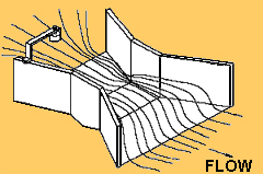
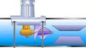
Vortex Flowmeters
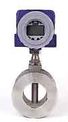
These meters are frequently used to measure steam flow as well as in other situations where wide flow ranges and high accuracy are needed, and where a meter with no moving parts is preferred.
A bluff bar element is placed in the meter’s flow tube which causes vortices to form downstream on either side of the bluff bar. The frequency of the vortices is proportional to the fluid velocity. The frequency is converted to pulses per unit of volume which a transmitter converts to an analog and/or digital output signal representing the flow rate.
Vortex meters are often used where wide flow ranges are expected. Turndown ratios as high as 100:1 are possible as compared to 3:1 with a non linear differential pressure element like an orifice plate. Accuracy is generally ± 0.5% to ± 1%. Sizes range from ½” to 12”. Approximate straight pipe run requirements are 20 pipe diameters upstream and 5 downstream.
Click here to request a quote or to see an application vortex flowmeter.
Thermal Mass Flowmeters

These meters are the fastest growing technology in gas flow measurement. They can provide stable and repeatable mass flow measurements with turndowns as high as 1000:1. They are widely used in low flow rate situations because of their high sensitivity to small changes in flow. There are two basic operating methods manufactured for industrial use: the Constant Temperature method and the Constant Power method.
The Constant Temperature sensor element consists of two matched RTD’s operating in a balanced state. One RTD acts as a temperature reference. The other RTD is a heated sensor. As molecules of moving gas come into contact with the heated RTD they absorb heat and cool it. As flow increases, more molecules contact the RTD which increases the heat loss. This heat loss tends to unbalance the flow sensor which is forced back into balance by the meter electronics.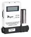 As more heat is dissipated, more power is needed to force the sensor back into balance. This power demand is directly proportional to the gas mass flow rate. With this method, only the skin temperature of the sensor is affected by the heat loss. This allows the sensor core temperature to be maintained which produces a very fast response to changes in the temperature and velocity of the media.
Additionally, with constant temperature meters, power is applied only as needed so the system has a wide temperature range. The effects of variations in density are virtually eliminated by molecular heat transfer and sensor temperature corrections. Meters using this method can provide a turndown ratio as high as 1000:1 when properly sized. Accuracy can range from ± 0.25% to ± 2%. Approximate straight run requirements are 5 pipe diameters upstream and 3 downstream.
The Constant Power method of thermal metering requires a sensor with three active elements. A constant current heating element is coupled to a heated RTD. A second RTD operates as an environmental temperature sensor. As with Constant Temperature meters the increasing flow velocity increases heat loss which is measured by the heated RTD. However in this method the temperature of the mass of the sensor must change in addition to the skin temperature causing it to be slower to respond to velocity changes.
The temperature of the heated RTD is electronically compared to the unheated RTD to determine the flow rate which is a function of the comparison. This method has a narrower useful temperature range because of the constant current applied. Meters using this method typically have a turndown ratio of 100:1. Accuracy can range from ± 0.25% to ± 2%. Approximate straight run requirements are 5 pipe diameters upstream and 3 downstream.
A very significant new feature with the Fox Thermal Gas Mass Flowmeter is a Cal-V in-situ calibration validation routine that validates the meter's calibration by testing the functionality of the sensor and its associated signal processing circuitry to meet federal and/or state regulatory requirements.
Click here to request a quote for a thermal mass flowmeter.
Variable Area Flowmeters
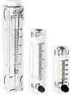
These meters are also called Rotameters. They normally consist of an acrylic or glass tube with a float that provides visual indication of flow rates on a linear scale which is on or next to the tube. Armored or all metal rotameters are available for high temperature and pressure applications.
Acrylic body models are an excellent low cost alternative for gas and liquid measurements where accuracy in the ± 2 to ± 5 % range is acceptable. The meters can be equipped with integral valves to adjust flow rates as well as with alarm switches or analog outputs. Sizes range from ¼” to 4” with turndown ratios of 10:1. Straight pipe runs are not required.
Click here to request a quote for a variable area flowmeter.
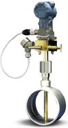
Insertion Flowmeters
Insertion flow meters are frequently used in large pipes where the physical size and weight and/or cost of a meter with a full body would be prohibitive. Annubars, Magnetic, Impeller, Paddlewheel, Thermal Dispersion, Turbine, and Vortex meters are all available as insertion style meters. Used mostly in pipe sizes 6 inches or larger, the insertion meters can be installed using flanged, threaded, or welded connections. Accuracy is generally ± 0.5% to ± 2%. Turndown ratios and straight pipe run requirements depend on the type of meter inserted.
In addition to easier installation and lower cost on large pipes, many insertion meters can be removed for maintenance and inspection without shutting down the flow. For high pressure lines, handwheel or drive screw units allow gradual withdrawal of the meter from an active pipe using an isolating ball or gate valve to close off the opening as the meter element is removed.
Click here to request a quote for an insertion flowmeter.
